RTD vs Thermistor: PT100 or NTC for Accuracy and Range
Oct 23, 2026Updated October 23, 2026. Reviewed by the Focusens Engineering Team.
| PT100 RTD | 10 kΩ NTC thermistor | |
|---|---|---|
| Sensing material | Platinum wire or film | Metal-oxide ceramic |
| Change per °C at 25 °C | +0.39 Ω (+0.35 % of its resistance) | −447 Ω (−4.5 % of its resistance) |
| Resistance curve | One standard curve (IEC 60751) | Set by each maker (B value or R-T table) |
| Tolerance at 25 °C | Class A ±0.20 °C, Class B ±0.43 °C | ±0.22 °C (±1 % R25, ±1 % B) |
| Tolerance at 100 °C | Class A ±0.35 °C, Class B ±0.80 °C | ±1.30 °C (±1 % R25, ±1 % B) |
| Typical rated range | −70 to +500 °C thin film, to +600 °C wire-wound (Class B) | −40 to +125/155 °C epoxy, to +200/300 °C glass |
| Error from 1 Ω of 2-wire lead at 25 °C | +2.6 °C | −0.002 °C |
| Connection | 3-wire or 4-wire for Class A or tighter | 2-wire |
Our calculation for the tolerance and lead rows, from the IEC 60751 class formulas and a Beta model with B25/85 = 3977 K. Ranges are the datasheet ratings cited in the range section below.
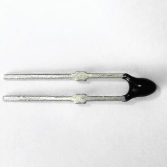
An RTD and a thermistor both turn temperature into resistance, but they are made of different materials and follow different curves. IEC 60751 defines the platinum resistor as a "resistor made from a platinum wire or film", and "a platinum resistor with R0 = 100 Ω is often referred to as a Pt100". A PT100 is therefore an RTD, not a thermistor. TDK describes NTC thermistors as resistors made of "polycrystalline mixed oxide ceramics" (TDK general technical information).
The materials behave in opposite directions. Platinum gains resistance as it warms, about 0.385 % per °C on average from 0 to 100 °C (the IEC 60751 α = 3.851 × 10⁻³ /°C). An NTC loses resistance as it warms, and much faster: TDK puts NTC coefficients at "2%/K to 6%/K", "about ten times greater than those of metals". Vishay's 10 kΩ NTCLE100E3 changes by −4.38 % per °C at 25 °C (Vishay NTCLE100E3).
| Temperature | 10 kΩ NTC (B 3977 K), per °C | PT100, per °C |
|---|---|---|
| 0 °C | −1,807 Ω (−5.3 %) | +0.391 Ω (+0.39 %) |
| 25 °C | −447 Ω (−4.5 %) | +0.388 Ω (+0.35 %) |
| 85 °C | −33 Ω (−3.1 %) | +0.381 Ω (+0.29 %) |
| 150 °C | −4.3 Ω (−2.2 %) | +0.374 Ω (+0.24 %) |
Our calculation: Beta model for the NTC, IEC 60751 equation for the PT100. Percentages are of each sensor's resistance at that temperature.
Comparing ohms per degree makes the gap look larger than it is. At 25 °C a 10 kΩ NTC changes about 1,150 times as many ohms per degree as a PT100, but relative to its own resistance it is about 12.7 times as sensitive. The relative figure is what the measuring circuit sees. The NTC's sensitivity also falls as it warms, from −5.3 % per °C at 0 °C to −2.2 % at 150 °C, while the PT100's stays between 0.24 and 0.39 %.
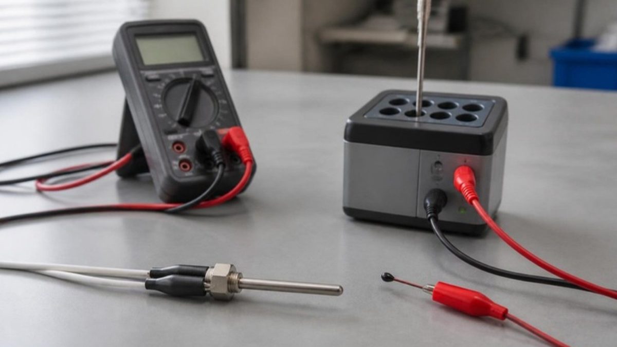
A Class A PT100 is more accurate than a standard 10 kΩ NTC at every temperature from −50 to 150 °C. A standard NTC beats a Class B PT100 only in a band around room temperature, and only the tightest NTC grades beat Class A, inside narrow windows. The table puts both on the same footing: worst-case tolerance in °C at each temperature. The NTC modelled is the 10 kΩ ±1 %, B25/85 = 3977 K standard parameter of our MF5A-4 epoxy NTC; its product page does not state a B tolerance, so the table shows ±1 % and ±0.5 % on B, each at its worst corner.
| Temperature | PT100 Class A | PT100 Class B | NTC ±1 % R25, ±1 % B | NTC ±1 % R25, ±0.5 % B |
|---|---|---|---|---|
| −40 °C | ±0.23 °C (wire-wound only) | ±0.50 °C | ±0.65 °C | ±0.39 °C |
| 0 °C | ±0.15 °C | ±0.30 °C | ±0.42 °C | ±0.30 °C |
| 25 °C | ±0.20 °C | ±0.43 °C | ±0.22 °C | ±0.22 °C |
| 50 °C | ±0.25 °C | ±0.55 °C | ±0.54 °C | ±0.40 °C |
| 85 °C | ±0.32 °C | ±0.73 °C | ±1.05 °C | ±0.69 °C |
| 100 °C | ±0.35 °C | ±0.80 °C | ±1.30 °C | ±0.82 °C |
| 150 °C | ±0.45 °C | ±1.05 °C | ±2.24 °C | ±1.34 °C |
Our calculation. PT100 columns: IEC 60751 Table 2, Class A ±(0.15 + 0.002|t|), Class B ±(0.3 + 0.005|t|); the same limits in °C apply to a PT1000. NTC columns: Beta model, B25/85 = 3977 K, worst of the four tolerance corners. Vishay's own tolerance method gives the same figures within 0.04 °C from 0 to 100 °C. Neither includes lead resistance, self-heating, drift or the instrument.
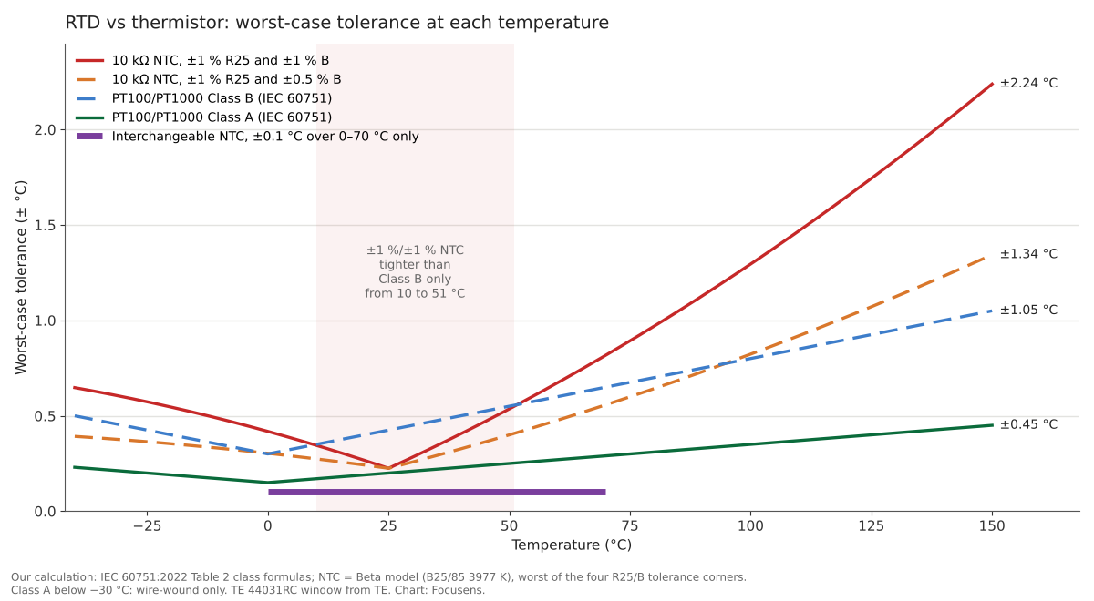
Three crossovers follow from the same calculation in 1 °C steps:
The NTC is tightest at 25 °C because that is where its resistance tolerance is specified. TDK explains why it spreads away from that point: "Due to this tolerance of the B value, an increase in resistance spread must be expected for temperatures that lie above or below the rated temperature." The platinum tolerance is smallest at 0 °C and grows by 0.002 °C (Class A) or 0.005 °C (Class B) per degree from there.
A ±0.1 °C thermistor spec covers a stated temperature window, and outside it the datasheet usually gives no figure at all. These are interchangeable NTCs, sold so that any part replaces any other on the same curve without recalibration. Every data sheet in the table below states its tightest tolerance over a window:
| Part | Tolerance | Window | Rated to |
|---|---|---|---|
| TE 44031RC, 44036RC (10 kΩ) | ±0.1 °C | 0 to 70 °C | 75 °C |
| TE 44006RC (10 kΩ) | ±0.2 °C | 0 to 70 °C | 150 °C |
| Amphenol MC65, grade A | ±0.05 °C | 35 to 39 °C | 105 °C |
| Amphenol MC65, grade A | ±0.15 °C | 0 to 50 °C | 105 °C |
| Focusens FHD4512 (precision NTC) | ±0.2 °C | 25 to 45 °C | 70 °C |
Sources: TE 44000RC series and TE 44006RC data (copies hosted by distributors), Amphenol MC65 and the Amphenol Type 65 datasheet, and our FHD4512 product page.
The ±0.1 °C TE parts hold that figure from 0 to 70 °C, and TE lists their best storage and working range as −80 to +75 °C, so the window covers the top of that range but nothing below 0 °C (an older MEAS summary lists 150 °C as the maximum for the same parts). The MC65's ±0.05 °C grade is a clinical part: it holds that figure across 4 °C around body temperature. Comparing it with a PT100 Class A figure that applies from −30 to +300 °C on a thin-film element is comparing two different things.
Platinum classes have windows too, and they are wide. IEC 60751 Table 2 sets Class A for film thermometers from −30 to +300 °C and Class B from −50 to +500 °C, and states that "thermometers or platinum resistors without the specified temperature range of validity for the tolerance are not permitted". Ask for the window whenever a thermistor accuracy figure arrives without one.
A standard coated or epoxy thermistor is rated to 125 °C (Vishay NTCLE100E3) or 155 °C (TDK B57861S), and a glass one to 200 to 300 °C; a platinum RTD runs to 500 °C as thin film and 600 °C or more wire-wound. Check the construction before the sensor type when the range is tight.
| Construction | Rated range | Source |
|---|---|---|
| Coated NTC | −40 to +125 °C continuous | Vishay NTCLE100E3 |
| Epoxy mini NTC | −55 to +155 °C | TDK B57861S |
| Glass-encapsulated NTC | −40 to +200 °C | Vishay NTCLG100E2 |
| Glass NTC for high temperature | up to 300 °C | TDK B57560G (distributor copy) |
| Thin-film PT100 / PT1000 | −70 to +500 °C | YAGEO Nexensos M222 |
| Wire-wound PT100, Class B | −196 to +600 °C | IEC 60751 Table 2 |
| Platinum curve definition | −200 to +850 °C | IEC 60751 scope |
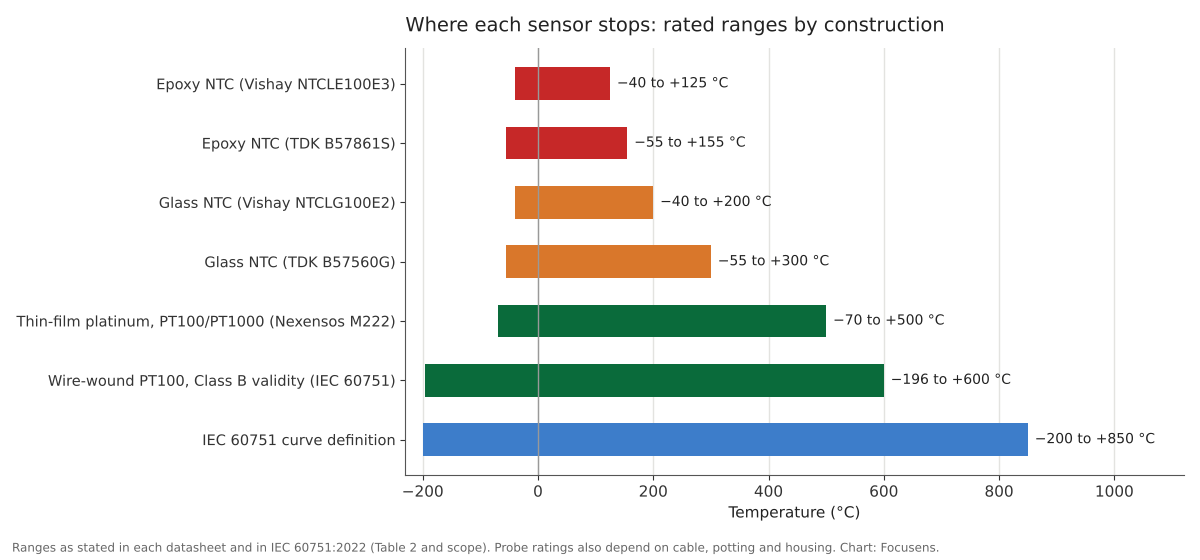
A probe can be rated lower than its element. The cable insulation, the potting compound and the housing all have limits of their own, which is why a glass NTC rated to 300 °C may sit in a probe rated to 120 °C. The tolerance class narrows the useful range of a platinum sensor further: IEC 60751 Table 2 allows Class A only from −30 to +300 °C on a thin-film element and from −100 to +450 °C on a wire-wound one, so a probe used at 500 °C can be Class B (thin film to +500 °C, wire-wound to +600 °C) or a declared special class, but not Class A.
Accuracy also falls away at the top of a glass thermistor's range. Vishay's own table puts its standard ±5 % glass NTCLG100E2 10 kΩ part at ±4.4 °C at 150 °C and ±6.2 °C at 200 °C, against ±1.05 °C and ±1.3 °C for a Class B PT100.
A PT100 is not linear, though it is far closer to linear than an NTC. The IEC 60751 equation above 0 °C is Rt = R0 (1 + At + Bt²), with a negative B term that bends the curve. Treating a PT100 as a straight line of 0.385 Ω per °C gives a reading off by −3.2 °C at −100 °C, +0.4 °C at 50 °C, −1.1 °C at 150 °C and −3.0 °C at 200 °C (our calculation). Microchip's RTD application note puts the nominal error of the same straight-line estimate at "smaller than 3.1°C" from −100 to +200 °C (Microchip AN687); the 2022 equation gives 3.2 °C at −100 °C, so read either figure as about 3 °C rather than as a bound.
An NTC curve is exponential, so an instrument needs the maker's curve to read it. Makers publish an R-T table or fit the Steinhart-Hart equation, and the simple Beta model holds only near its two reference points; TDK says it "is only suitable for describing a restricted range around the rated temperature". On a Vishay 10 kΩ part the Beta model alone is off by +0.8 °C at 0 °C and +2.8 °C at 150 °C (our calculation). Microchip AN685 lists the ways a circuit applies the curve: a third-order polynomial or a look-up table in software, or a series or parallel resistor that straightens the output; for the series circuit, "if high precision is required, this range is typically +/-25°C around the nominal temperature". Whichever method the controller uses, the curve it holds must match the part.
NTC data sheets give resistance changes of typically under 2 % (TDK B57861S epoxy, 1000 h at 155 °C) to at most 3 % (our MFT probes, 1000 h heat or cold store) after 1000 hours, which is about 0.45 to 0.7 °C at 25 °C; a thin-film PT100 typically drifts about 0.1 °C after 1000 hours at 500 °C. The two are tested under very different conditions, so treat the comparison as an order of magnitude.
| Part and test | Datasheet figure | In °C (our calculation) |
|---|---|---|
| TDK B57861S epoxy NTC, 155 °C, 1000 h | ΔR25 typically < 2 % | about 0.45 °C at 25 °C |
| TDK B57861S, 70 °C, 10,000 h | < 2 % | about 0.45 °C at 25 °C |
| Focusens NTC probes (MFT series), heat or cold store 80 °C / −30 °C, 1000 h | drift ≤ 3 % | up to 0.68 °C at 25 °C |
| TDK B57560G glass NTC, 300 °C, 1000 h | ΔR25 typically < 3 % | about 0.7 °C at 25 °C |
| MEAS 44005 interchangeable NTC, held at 100 °C | 0.20 °C after 10 months | 0.20 °C at 100 °C |
| MEAS 44005, held at 150 °C | 1.5 °C after 10 months | 1.5 °C at 150 °C |
| YAGEO Nexensos M222 thin-film platinum, 500 °C, 1000 h | typical 0.04 % of R(0 °C) | about 0.10 °C at 0 °C |
Sources: TDK B57861S, our MFT series product page, TDK B57560G (distributor copy), MEAS 44000 series summary (distributor copy), Nexensos M222.
The MEAS figures show how much drift depends on temperature: the same interchangeable NTC that drifts 0.20 °C at 100 °C drifts 1.5 °C at 150 °C, and the datasheet marks 150 °C "Not recommended" for long service. TDK names the causes of this ageing as "thermal stress", "oxygen exchange with the environment (with unprotected, non-glass-encapsulated thermistors)" and "diffusion in the contact areas", and notes that the reactions slow at low temperatures and speed up at high ones. For a sensor that will sit above 100 °C for years, platinum is the safer choice; a glass NTC is the thermistor option if the range allows it.
Lead wires matter far more for a PT100 than for a 10 kΩ NTC, and they push the readings in opposite directions. Extra series resistance looks like a warmer platinum element and like a colder NTC.
| Temperature | PT100, 1 Ω added | PT1000, 1 Ω added | 10 kΩ NTC, 1 Ω added |
|---|---|---|---|
| 0 °C | +2.56 °C | +0.26 °C | −0.0006 °C |
| 25 °C | +2.58 °C | +0.26 °C | −0.002 °C |
| 85 °C | +2.63 °C | +0.26 °C | −0.030 °C |
Our calculation for a 2-wire connection, using the slopes from the sensitivity table.
One ohm is about 6 m of 24 AWG two-core cable (10 m adds 1.68 Ω, as tabulated in our PT100 vs PT1000 comparison), so a 2-wire PT100 picks up degrees of error. IEC 60751 therefore requires "3-wire or 4-wire configuration" for thermometers of a class better than B. A 10 kΩ NTC loses only a few thousandths of a degree per ohm at room temperature, although the error grows about 13 times by 85 °C as its resistance falls to about 1 kΩ. The cable arithmetic for platinum is in our page on RTD lead resistance error, and the NTC case in our thermistor wiring guide. A PT1000 cuts the platinum lead error to a tenth, which is the main argument for it.
Self-heating is small for a PT100 at its usual 1 mA, but on a common divider an NTC's self-heating can exceed its own tolerance, depending on the package. A thin-film PT100 at 1 mA dissipates 0.1 mW and warms about 0.04 °C at the 0.4 K/mW (at 0 °C, medium not stated) that Nexensos gives for its M222 element. That is just above the 0.0375 °C that a 25 % share of the Class A tolerance at 0 °C allows, one reason Nexensos recommends 0.3 to 1 mA for a Pt100. IEC 60751 caps self-heating at 25 % of the class tolerance and notes the current "is usually not more than 1 mA" for a 100 Ω wire-wound resistor. A 10 kΩ NTC in a 3.3 V divider with a 10 kΩ fixed resistor dissipates 0.27 mW at 25 °C, which is 0.04 to 0.54 °C depending on its dissipation constant: Vishay 7 mW/K for the larger NTCLE100E3, TDK about 1.5 mW/K for the B57861S, TE 1 mW/°C in still air for its 44000RC beads and Amphenol 0.5 mW/°C for the small MC65 bead (our calculation). The divider is a common microcontroller circuit, so the package's dissipation constant, not the sensor type, sets the error here.
Every PT100 made to IEC 60751 follows the same curve, so such a PT100 from any maker reads correctly on an input set for that curve; when replacing a sensor, check that both state that standard and α = 3.851 × 10⁻³ /°C. NTC curves differ by maker and by ceramic. Parts that all read 10 kΩ at 25 °C can differ by almost 2 °C at 0 °C:
| 10 kΩ NTC curve | Resistance at 0 °C | Reading offset at 0 °C on a Vishay curve |
|---|---|---|
| Vishay NTCLE100E3, B25/85 3977 K | 32,554 Ω | 0 |
| TDK curve 8016, B25/100 3988 K | 32,650 Ω | −0.06 °C |
| Amphenol MC65, material F (3969 K) | 32,740 Ω | −0.11 °C |
| Amphenol MC65, material Y (3690 K) | 29,566 Ω | +1.89 °C |
Datasheet resistances; offsets are our calculation. A part with more resistance at 0 °C than the Vishay curve expects reads cold; one with less reads warm.
On an NTC replacement, the curve has to match as well as R25. Our 10k thermistor chart shows the bigger mix-up: a Type 2 sensor on a Type 3 input reads about 2 °C low at 0 °C and about 7 °C high at 100 °C. Microchip's thermistor note states the general rule: "Each vendor carefully specifies their thermistor characteristics with temperature, depending on their manufacturing process" (Microchip AN685).
An RTD and a PTC thermistor both rise in resistance with temperature, but a ceramic PTC switches while platinum measures. Murata describes the ceramic PTC: barium titanate "changes its crystal structure around the Curie temperature", and above it "the resistance value increases" steeply (Murata). That jump makes a PTC a trip device, which is why motor windings use PTC thermistors with a protection relay; our page on motor PTC thermistors covers the trip values.
| Sensor | Material | Behaviour | Typical job |
|---|---|---|---|
| PT100 / PT1000 RTD | Platinum | +0.39 % per °C, standard curve | Measurement, −200 to +850 °C curve |
| Ceramic (switching) PTC | Barium titanate | Flat, then a steep rise at a designed temperature | Over-temperature trip, resettable fuse |
| Silicon linear PTC (KTY) | Silicon | +0.79 % per °C at 25 °C | Measurement, −55 to +150 °C |
Sources: IEC 60751, Murata, Philips KTY81-2 datasheet (university mirror).
A PT1000 has a positive temperature coefficient, but it is not a PTC thermistor. The silicon KTY sits between the two: it measures like an RTD on its own curve, and drives that expect a KTY84 read a PT1000 wrongly, as shown in our page on KTY84 vs PT1000 inputs.
Choose an RTD for wide spans, temperatures above about 150 °C, long-term stability at heat and one interchangeable curve; choose an NTC thermistor for narrow spans near room temperature, small size and simple 2-wire electronics. Response time depends on the package more than on the sensor type.
| If your application has… | Choose | Why |
|---|---|---|
| A span wider than about 100 °C, or readings above 150 °C | PT100 or PT1000 | Tolerance grows slowly; epoxy NTCs stop at 125 to 155 °C |
| Long service above 100 °C | PT100 or PT1000 | Platinum drift is about 0.1 °C after 1000 h at 500 °C |
| Instruments or spare sensors from several suppliers | PT100 or PT1000 | One IEC 60751 curve |
| A narrow span around 0 to 70 °C and tight accuracy | Interchangeable NTC | ±0.1 to ±0.2 °C inside the window |
| A long 2-wire cable | NTC, or a PT1000 | Lead error is negligible on a 10 kΩ NTC |
| Battery power or a microcontroller ADC | NTC, or a PT1000 at low current | Large signal from a simple divider |
| An over-temperature trip, not a reading | Ceramic PTC thermistor | Switching curve, relay input |
| An existing controller or input card | Whatever it is set for | Wrong curve gives degrees of error or a sensor fault |
The system cost follows the same split. A PT100 needs an RTD input or transmitter and, for Class A or tighter, 3-wire or 4-wire cable; an NTC needs only a divider and its curve in the controller.
Response time follows the package. Vishay gives about 1.2 s in oil and a 15 s thermal time constant for its coated NTCLE100E3 bead, and a 0.9 s response time (medium not stated) and 6 s time constant for the glass NTCLG100E2; Nexensos gives t0.5 = 0.05 s in water at 0.4 m/s and 3 s in air at 2 m/s for the bare M222 platinum element. Our catalog lists a time constant of up to 30 s in water for the MFT NTC probe in a plastic housing and about 10 s for the PT100 Class B probe. The test media differ, so compare constructions, not sensor types. Where a reading above 600 °C is needed, a thermocouple is the usual answer; our thermistor vs thermocouple and thermocouple vs RTD pages compare those pairs.
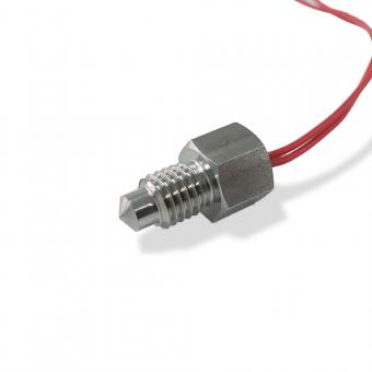
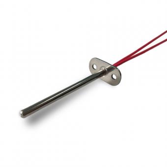
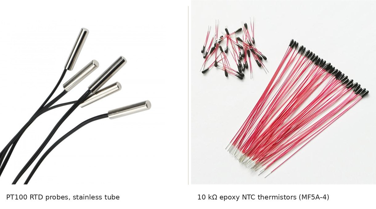
Focusens makes both families as probes and assemblies. Our platinum probes use PT100, PT500 or PT1000 elements with working ranges of −50 to 300 °C or −50 to 500 °C, to Class B ±(0.3 + 0.005|t|) or, inside the range IEC 60751 allows for it (−30 to +300 °C on thin-film elements, −100 to +450 °C wire-wound), Class A ±(0.15 + 0.002|t|); see the PT100 Class B probe and the RTD sensor range. On the NTC side, the MF5A-4 epoxy NTC uses 10 kΩ ±1 % with B25/85 = 3977 K or 3435 K as standard, and the precision NTC range includes interchangeable parts at ±0.2 °C from 25 to 45 °C.
To get a quotation that matches, specify:
Send us those details with the input the sensor will connect to.
A PT100 is an RTD, not a thermistor. IEC 60751 defines it as a platinum resistor with a resistance of 100 Ω at 0 °C. Most thermistors are ceramic semiconductors with much steeper, maker-specific curves.
A PT1000 has a positive temperature coefficient: its resistance rises about 0.39 % per °C. It is still not a PTC thermistor, which is a ceramic part that switches sharply at a designed temperature. A PT1000 is a platinum RTD on the IEC 60751 curve.
An RTD is platinum, rises about 0.39 % per °C and follows one standard curve. An NTC is a metal-oxide ceramic, falls about 4.5 % per °C at 25 °C and follows its maker's curve. The RTD keeps its tolerance over a wide range; the NTC is most accurate near 25 °C.
A platinum RTD measures temperature on a smooth, standard curve. A ceramic PTC thermistor stays fairly flat and then jumps in resistance at a designed temperature, so it is used to trip a relay or limit current. Silicon linear PTCs such as the KTY measure, but on their own curve.
A thermistor is more accurate than an RTD only inside a narrow band around room temperature. A 10 kΩ NTC with ±1 % on R25 and on B beats a Class B PT100 only from about 10 to 51 °C and is never tighter than Class A. Interchangeable NTCs specified at ±0.1 °C beat Class A inside their 0 to 70 °C window; outside it their data sheets give no figure (our calculation).
An RTD is more accurate wherever a Class A element is allowed (to +300 °C thin film, +450 °C wire-wound): a Class A PT100 is ±0.35 °C at 100 °C, while a class 1 type K thermocouple is allowed ±1.5 °C from −40 to 375 °C and ±0.4 % of the temperature above that under IEC 60584-1:2013 (tolerance table reproduced by TC Direct). Above about 240 °C a Class B PT100 is looser than a class 1 type K (±2.8 °C against ±2.0 °C at 500 °C, our calculation), and above the platinum range a thermocouple is the usual choice; see thermocouple vs RTD.
A glass-encapsulated thermistor can measure above 150 °C: Vishay rates its NTCLG100E2 to 200 °C and TDK sells glass NTCs for up to 300 °C. Standard coated or epoxy NTCs are rated to 125 to 155 °C. Tolerance widens at the top of the range: Vishay's ±5 % glass part is ±4.4 °C at 150 °C.
Drafted with AI assistance from the standards and data sheets linked above; the Focusens Engineering Team checked the figures against those sources and our product data on October 23, 2026. Tolerance classes, the platinum curve and wiring rules come from IEC 60751:2022; NTC figures from the Vishay, TDK, TE, Amphenol and MEAS documents linked above. Figures marked "our calculation" are computed from those sources and are not bench measurements.
No.1 XiSan Road, Electromechanical Industry Park , High&New Tech.Zone. Hefei,Anhui,China
tel : +86-551-69109668
Whatsapp : +86-13339100504
e-posta : info@focusens.com
Skype : melodyliu520






 +86-551-69109668